Language:
 ∷
∷

∷
 ∷
∷
Home > Lightning Impulse Generator
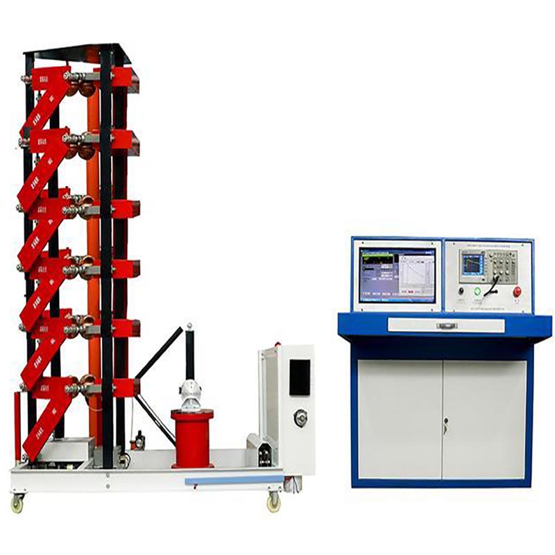
1.Application
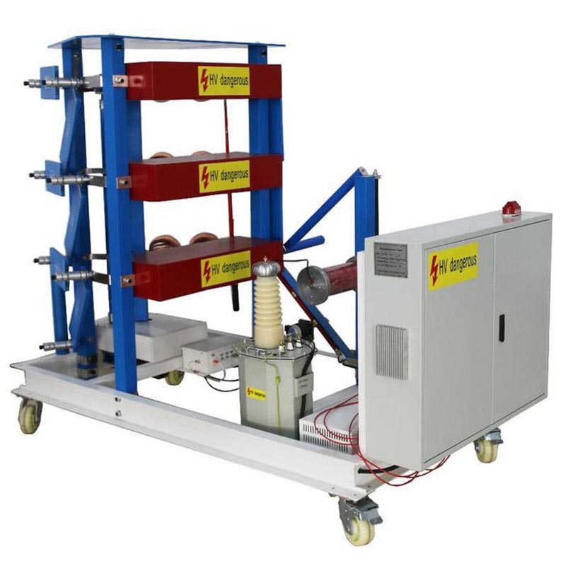
The equipment can be used to the standard lighting impulse voltage full-wave ,steep wave and other impulse test of the test products such as used for the air gap, cable and accessories, insulator strings, casing, power transformers and transformer generator and so on.
2.The note of the programming
The sets of equipment mainly used for the needs of synthesis of full-wave lightning insulator test and steep wave . The basic configuration of the sets of the equipment is composing of charging devices, impulse voltage generator body, the impact of weakly damped capacitive divider, steep device, precision resistor divider Express, control devices, measuring devices. Basic configuration for the controlleris the digital oscilloscope; Ontology HIGHVOLT H-type structure.
3.Operation Requirements
-Amplitude : ≤1000m
-Temperature: -5℃~+40℃
-Day temperture different : ≤25℃
-Humidity : ≤85%
-Ground level acceleration 3.0m/s2, vertical ground acceleration 1.5m/s2
-No conductor dirty
-No fire and explode
-No corrosive gas
-Sine power source, the total distortion <5%
-Earthing resistance less than 0.5Ω
-Install Location: Indoor
4.Standard
-IEC 60060-1
-IEC 60076-3
-IEC 62271-1
-IEC 62271-200
5.The list of equipment
1)Impulse generator body 37.5kJ/600kV 1 set
2)±100kV charging device 1 set
3) 600KV/300Pf impulse weak damping divider 1 set
4) 600kV steep device 1 set
5) 600kV steep wave resistance voltage divider 1 set
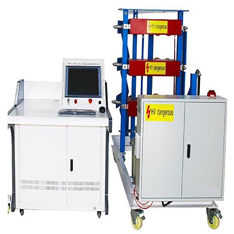
6) Manual / Automatic Controller 1 set
7) TDS-3012B tektronix memory oscilloscope 1 set
8) Attachment (including two meters grounding rods and 5 metersbraided copper wire, 40 meters grounding copper etc.) 1 set
9) Power and cable are configurated at the scene. Cables including control and measurement are provided by the seller (size is offereed under the confirm of the buyer).
6.Main technique parameters
1)Rated voltage : ±600kV
2)Rated stage voltage : ±100kV
3)Rated energy :37.5 KJ
4)Capacitance : 0.2081μF
5)Totel grade: 6
6)Capacitance per stage:1.25μF (2.5Χ2μF/50kV)
7)Impulse voltage shape:
When load capacitance is between 300~5000pF T1=1.2μS±30%、T2=50μS±20%、Up≤3% full lightning impulse voltage; The gradient of the steep shape: >2500 kV/μs, Up>500 kV。The impulse voltage can fit the GB/T 311.1, GB/T 16927.1and IEC standards。
8)Efficiency:For full lightning η≥90% when the load capacitance is less than 1000pF, For full lightning η≥85% when the load capacitance is less than 2000pF.
![]() 9)The synchronism range less than 20% when the charging voltage is between 20%~100%;
9)The synchronism range less than 20% when the charging voltage is between 20%~100%;
10)Discharge failure:<5%
11)Lowest output voltage:≥±20% rated voltage
12)Charging voltage uncertainty:<±1.0%
13)Operation time: 90s used upper 2/3 rated voltage; 45s used below 2/3 rated voltage.
7.Description of structure
1).Charging part
(1)Constant charging: rated output voltage ±100kV rated output current 10-100mA
(2) Transformer charging oil immersed,
primary voltage 220V,Secondary voltage 80kV,rated capacity 8kVA, No leakage oil.
(3) The silicon installed on the charging plant is 2DL-200kV/200mA high –voltage rectifier, reverse voltage ≥200kV, the average current ≥ 0.2A.
(4) Protective resistors of the high -voltage silicon rectifier are made of enamelled resistors
(5) When constant-current charge devices at the range of 15% ~ 100% rated voltage , the deviation between the actual charging voltage and the tuning voltage is less than ± 1%, the uncertainty of charging voltage is less ± 1%, and the adjustable precision of charge voltage is 1%;
(6) HVDC resistance divider : 150kV,300MΩ , High-pressure glass glaze resistor and Low-voltage arm resistance loaded at the bottem of the divider , voltage signal on the low-voltage arm introduced to the measure system with the shielded cables .
(7)Automatic earth system can earth the capacitors and the high voltage when the test hangs.
(8) Constant current charging device, charger transformers, high voltage rectifier, and voltage capacitor, resistor divider, charge current limiting resistor and the mainly installed in the same mobile chassis;
(9) The devices not only can be used as charging power supply of the impulse voltage generator, but also can be used as 150 kV DC voltage generator , use to test other DC Products.
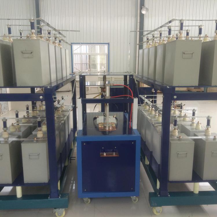
![]() 2).Main body
2).Main body
(1)The contracture of the generator is HIGHVOLT H and G type .
(2)Double-voltage charging unit and stage voltage is 100KV .
(3) 10 grade stages, every stage is made of two pcs of 2 台 MWF50kV-2.5μF μF capacitor, charging resistor, the front resistor, the tail resistor and the sphere gaps. The resistors can be replaced when the load capacitance is changed.
(4) Level impulse capacitor is1.25 ± 0.01mF, DC working voltage ± 100kV, the residual inductance capacitors less than 0.15mH, the capacitor casing can withstand the vertical pull 15kg, while guaranteeing not to damage and leakage of oil; capacitor casing to withstand the level of qualified pull 15kg . At the same time, ensure that no damage and leakage of oil, the installed of the capacitors without deformation.
(5) The front and the tail resistors are made with plate structure (see right pictures). The resistors have low inductance.
(6) The connectors of the resistors are push and plug design
(7) The resistors can be used parallel;
(8) The first sphere-gap use double polarity trigger pulse for reliable trigger;the second
to the tenth use Gap oval ball ignition, thus ensuring the reliability of the trigger;
(9) The distance of the sphere gaps is derived by electrical motor for high precision. ,
no noisy, positioning without inertia, accurate, fast, control discharge voltage corresponds to the ball gap .
(10) The distance of the sphere gaps can be changed automatically or manual;
(11) The generators can be used 2~9 stages for low output;
(12) The backbone of the generator is made of glass fiber reinforce plastic
(13)Anti-corona solutions.
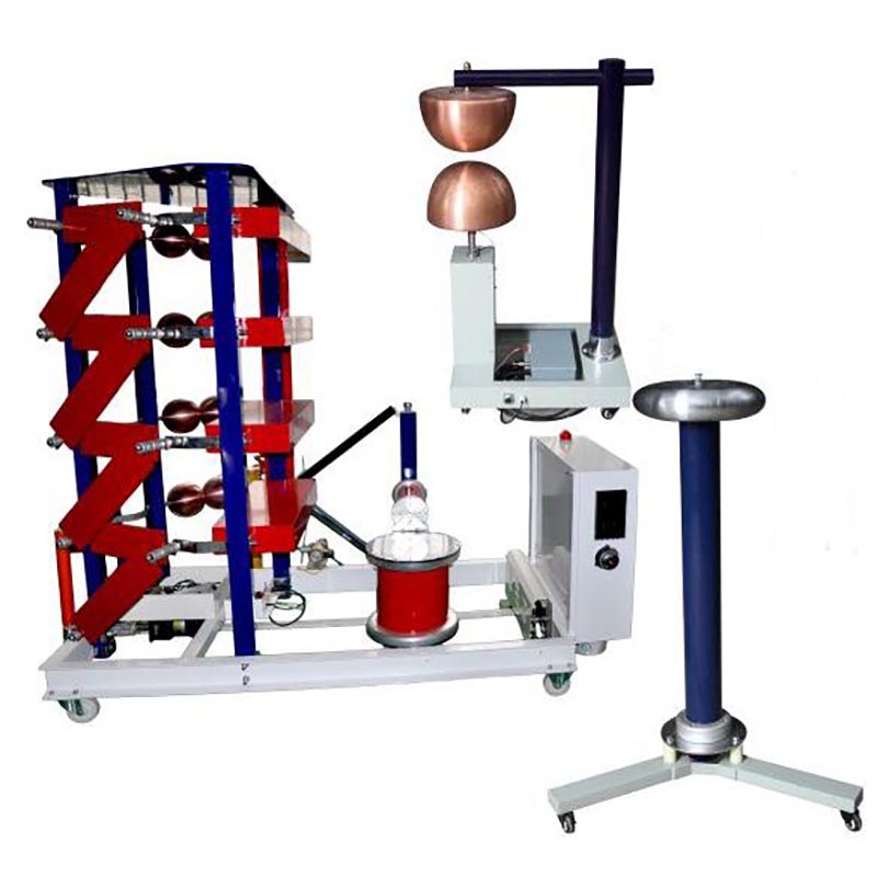
3).600KV Low-damp divider
(1)The high voltage capacitor compose of 1 grades ,the rated parameters is 600kV/300pF.
(2)Rated Lightning Impulse voltage tolerance
600KV;
(3)Pressure divider ratio: 2000:1 (2 low-voltage arm)
(4)Uncertain measurement : less than 1%;
(5)Weakly damping capacitive divider of the square-wave meet the standard requirements of the GB/ T 311.1 and GB / T 16927.2
4).600KV Steep IV Unit
The steep IV units includes the steep capacitor, the sphere-gap ,the driving system and the base-plane .The parameters of the steep capacitance is 300Pf/ 600KV .The ball gap can meet the needs of composite insulator test , that is the steepness more than2500 kV / ms, the maximum steepness can go to 4000 kV / ms.
5).600kV composite insulator steep wave resistor divider
High-voltage about 2.5 KV , low-voltage about 0.8 V. Rated working voltage 600kV, some parts of square-wave response time less than 10 ns, the stability time less than 400 ns.
6). Manual / Auto controller
Including the manual and auto two parts, Manual and Automatic functions
(1) Auto-ground and auto-relief charging equipment
(2) Sphere gap distance change
(3) Constant charging
(4) Charge voltage auto/manual change
(5) Manual/auto trigger
![]() (6) Manual / Auto alarm
(6) Manual / Auto alarm
(7) Over-current and over-voltage protection
Indicators for controller
(1)Charging transformer input current instructions
(2) Charging transformer input voltage instruction
(3)Turing voltage digital instruction
(4) First-class capacitor charging voltage digital instructions
(5) Trigger gap ball instructions
(6) Cut-off wave gap ball instructions
(8) Other lighting and symbols
8.Acceptance contact
1)The general requirements
-The connections of the cables between the equipments
-The automatic tracking of the frist level ball gap
-Transmission function
-Lighting function
-Automatic grounding function
-Charging devices function
-Adjust function of charging time and voltage
-The range of the first level ball gap is less than 20%.
-The Supplier fully responsible for the installation and debugging, including re-wiring and debugging of the original equipment chassis
-The supplier should have training meet the needs of the demand-side at the scene.
-Checking Appearance : When equipment characteristic qualified , the demand-side should signature on the test report .
2)Impulse equipment body
-Measurement of output voltage waveform
-Measurement of input, output voltage and current
-Measurement of input ,output power and efficiency
-Check the heat situation of each connection
-Setting over voltage test
-Breakdown protection test
-Emergency stop test
-Equipment flashover test :Flashover impulse the equipment when it with full load . Repeat 3 times of the above steps should be normal action.
3)Test of all the fittings
-Measurement of charge resistance, the first wave resistance, wave tail resistance, grounding resistance of the DC resistance and insulation resistance
-Measuring the impact of capacity and electric capacitor dielectric loss angle Voltage test
4)Test voltage divider
-Resistance measurement, and the different between the design value less than ± 1%
-Voltage test
-Divider ratio test, shall award the metrological verification certificate from country or authority department of the power system.
5)Charging Transformer and the rectifier device test
-Measurement of charge transformer DC resistance and insulation resistance and variable than the situation
-Measurement of the RP-rectifier device breakdown voltage
-Voltage test
6)Steep device acceptance
-Resistance measurement, the difference with the design value difference ± 1%,
-Square-wave response to the correct of the calibration
-Partial pressure test
-Voltage test
7)Manual, automatic ball-gap synchronous linkage test
Contact: Mr.Luo
Phone: 86 13071289809
Tel: 86-27-82423362
Email: goldsol@foxmail.com
Add: No.128, Sanyang Road,Hankou Wuhan