Language:
 ∷
∷

∷
 ∷
∷
Home > PD test System
Application:
- 220KV GIS Breaker or below;
- 220KV CT/PT or below ;
- 220KV Bushing or below ;
- 220KV Insulators, disconnectors or below;
- 220kV CB or below;
- 220KV Insulation Instrument or below
- 220KV cables
General working conditions
1.Elevation ≤1000m;
2.Use ambient temperature: 0℃~40℃
3.Storage temperature: -20℃~+50℃
4.Maximum Daily Temperature Difference: <25℃
5.Relative humidity: ≤ 90%(25℃)
6.Sunshine intensity: 0.1W/cm2(wind speed 0.5m/s)
7.Seismic strength: horizontal: 0.2g; vertical: 0.1g
8.Location of use: indoor and outdoor
9.No fire and explosion hazards
10.Existence of gases that do not contain corrosive metals and insulation
11.A reliable grounding point with grounding resistance less than 0.5 ohms
12.Flat place of Installation, inclination is less than 5 degrees.
13.Seismic Resistance ≤ 7 class
Compliance with Standards
1.JB/T9641-1999 Test Transformer
2.GB10229-88 Reactor
3.DL-T615-1997 Guidelines for Selection of AC High Voltage Circuit Breaker Parameters
4.GB/T.311.1-1997 Insulation and Coordination of High Voltage Transmission and Transformer Equipment
5.GB/T16927.1-1997 High Voltage Test Technology Part I General Test Requirements
6.GB/T16927.2-1997 High Voltage Test Technology Part II
7.GB1094.1-1996 Power Transformer Part I General Provisions
8.DL/T 848.2-2002 General Technical Conditions for High Voltage Testing Devices Part 2: Power Frequency High Voltage Testing Devices
9.DL/T 848.3-2002 General Technical Conditions for High Voltage Test Devices Part 3: Transformers without Partial Discharge Test
10.DL/T849.6-2004 General Technical Conditions for Special Testing Instruments for Electric Power Equipment Part 6: High Voltage Resonance Testing Devices
11.DL/T 846.1-2002 General Technical Conditions for High Voltage Test Equipment Part 1: High Voltage Voltage Divider Measurement System
12.DL/T 596-1996 Preventive Test Rules for Electric Power Equipment
13.GB2536-1990 Transformer Oil
14.GB7328-1987 Sound Level Measurement of Transformers and Reactors
15.JB8749-1998 General Technical Requirements for Voltage Regulators
16.JB/T7070.15 Voltage Regulator Test Guidelines Part I
17.JB/T563-1999 Technical Specifications for Order of Coupled Capacitors and Capacitance Voltage Dividers
18.JB/T8169-1999 Coupled Capacitor and Capacitor Voltage Divider
19.GB4208-1993 Shell Protection Level
20.GB/T191-2000 Picture Signs for Shipping, Storage and Transportation
All bolts, double-head bolts, threads, pipe threads, bolt clamps and nuts shall comply with the standards of the International Organization for Standardization (ISO) and the International System of Units (SI).
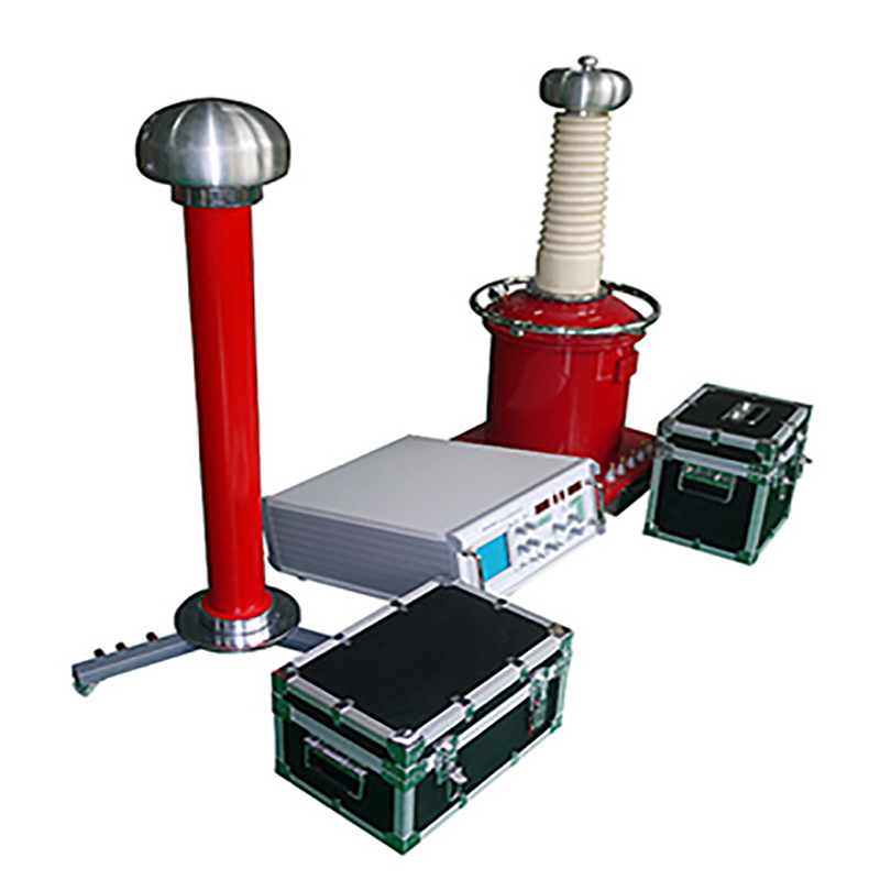
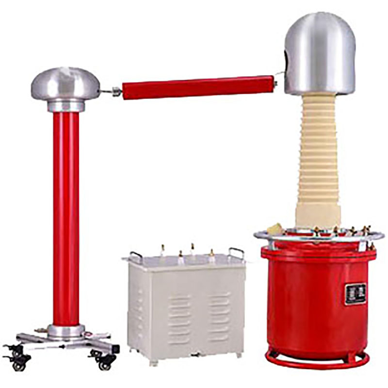
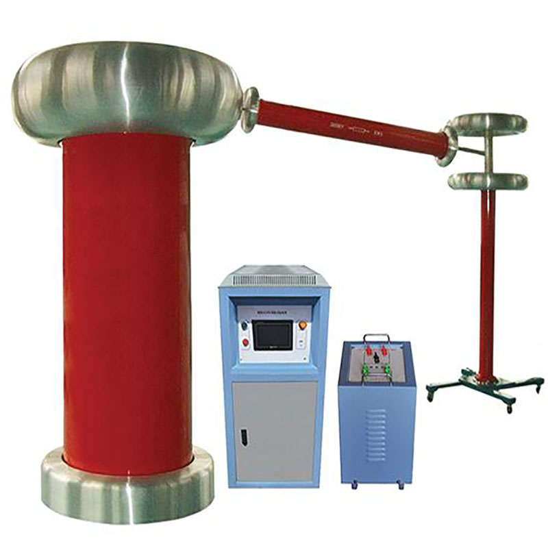
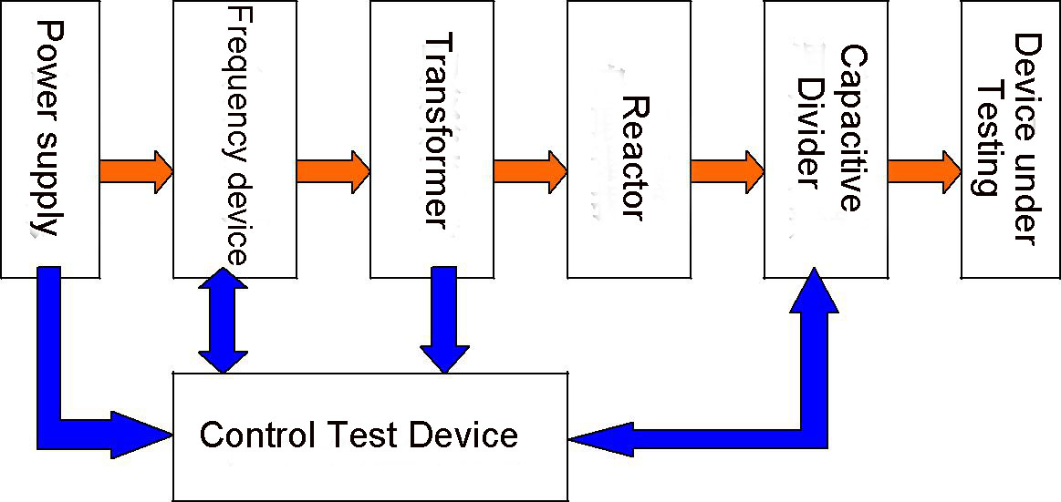
Schematic diagram
Parameters of Full System
1. Rated output capacity: 500Kar (resonant state) (2*250kvar/250KV reactors in series);
2. Rated voltage and current: 250 kV/1A;
3. Rated input voltage and current: 380V, 78.9A three-phase;
4. Output Voltage: 0kV-500kV; Output Voltage Instability ≤ 1%;
5. Frequency regulation range: 20-300 Hz
6. Frequency resolution: 0.1Hz
7. Frequency instability: ≤ 0.05%
8. Output Voltage Waveform: Sinusoidal Waveform, Output Waveform Distortion Rate ≤ 1%
9. Running time: 30 minutes
10. Temperature Rise: Component Temperature for Continuous Operation for 30 Minutes at Rated Capacity ≤ 65K
11. Noise: ≤ 65dB
12. Partial Discharge: ≤ 10Pc at rated voltage
13. Frequency instability ≤ 0.02Hz
14. Converter power supply capacity 30 kW
15. Insulation level: 1.1 times rated voltage withstanding 1 minute
16. Quality Factor: More than 40 at 50Hz
17. Over-current, over-voltage and flashover protection functions for the tested products
18. System Measurement Accuracy: RMS Level 1
System configuration and parameters
|
Sr no |
Description |
Specification |
Qty |
|
1 |
PD Frequency Power Supply Device |
30KVA |
1 unit |
|
2 |
Excitation Transformer |
30/2*15/2*0.35 |
1 unit |
|
3 |
FM Series Resonant Reactor |
250KVA/250KV |
2 units |
|
4 |
Capacitive Divider |
500kV/400pF |
1 unit |
|
5 |
Control test cable |
|
1set |
|
6 |
Accessories & Equalizing ball |
|
1 set |
|
7
|
PD Shielding Room (Ferrari cage) |
For optional |
1 set |
|
Control Room |
|||
|
Insulated Floor |
1. PD Frequency Power Supply Device
1) PD frequency power supply device including following devices:
|
Name |
Description |
Specification |
Qty |
|
Power frequency power supply |
PD Frequency Power Supply Device |
30KVA |
1 unit |
|
Frequency Power Supply Controller |
30KVA |
1 unit |
|
|
Frequency Converter Cabinet Control Optical Fiber |
20m(Photoelectric Converter included) |
1 unit |
|
|
HV Measurement Optical Fiber |
20m |
1 unit |
|
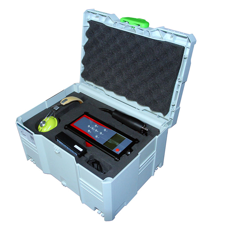
|
High Voltage Measurement Terminal |
|
1 unit |
2) Main parameter
- Rated input power supply: three-phase AC380V + 10%, 50Hz
- Rated output voltage: single-phase 0-350V AC
- Rated output current: 0-78.9A
- Rated output power: 30 kW (maximum output active power)
- Output frequency: 20-300 Hz continuously adjustable
- Frequency regulation accuracy: 0.1Hz
- Continuous working hours under full load: 60 minutes
- Output waveform: standard sine wave, waveform distortion ≤3%.
- Output Voltage Instability: ≤1%
- Noise level: < 75dB
- Cooling mode: forced air cooling
- Insulation level: input and output terminals to ground (> 2kV/AC/1min)
- Permissible temperature rise: under rated load, continuous operation for 60minutes, constant voltage output when outlet temperature rise is less than 60K frequency is adjusted within a set range
3) Advantage
A.Basic advantage:
- Frequency conversion power supply,control box, divider are connected by optical fibre, which completely isolates high and low voltage, and ensures safe operation.
- Ontology is separated from control, display and protection. Ontology and protection are integrated, while control and display are integrated, which is easy to carry on site.
- Frequency conversion power supply has the ability of resisting electric field interference. Under the strong electric field interference, the measurement accuracy and control protection meet the requirements. It has good magnetic shielding, high magnetic conductivity material is used for shielding components and leads, and there is no space radiation.
- Because of the poor temperature performance of high power transistors, the temperature rise increases and the amplification factor of transistors increases when the output power is larger, which leads to the output voltage drift. It depends on the constant adjustment of the output voltage by the experimenters. This problem can not be solved by the early products. Now the software of single chip computer is used to realize the automatic voltage adjustment to ensure the stability of the output voltage.
- The signal source of the variable frequency power supply is produced by a special chip and controlled by a single chip computer. The output frequency is stable and the adjustment is more fine. All the data are displayed on a large LCD screen.
- The main body of the power cabinet and the control box, the voltage divider and the control box of the variable frequency power supply are connected by optical fibers, which completely isolates the power cabinet, avoids the damage of the control box caused by the counterattack after the sample breaks down, and is safer to use. The special optical fibers are used to connect the optical fibers, which can withstand the destruction of various natural and human factors. It is especially suitable for on-site withstand voltage test of high voltage long cable and large capacitance test.
B. Control function
- There are start, stop and emergency switch buttons.
- There are boost and reduce adjusting buttons (the rate of boost and reduce button can be set), and frequency adjusting buttons (the rate of regulation can be set).
- Automatic and manual test selection (automatic tuning, automatic boost and reduce, etc.).
- It has the function of automatic and manual test mode selection. The automatic test mode is setting test voltage and test time, automatic tuning-automatic boost-automatic constant withstand voltage and timing-automatic step-down. Automatic tuning and timing can also be used in manual test.
- It has the functions of output voltage, over-voltage protection and setting value adjustment of over-current protection.
- It has the function of setting test time, timing accuracy (±0.1 seconds), and provides sound prompt for the tester at the end of the time period.
C.Screen Display Function
- Display of bridge arm voltage of power amplifier;
- Output voltage, current and frequency of variable frequency power supply are displayed.
- All kinds of protection action display;
- High voltage voltage measurement;
- The measurement of high voltage voltage (the measurement signal of high voltage divider is connected to the control box by optical fibers, and the optical fibers are connected by military field optical fibers, which can withstand the destruction of various natural and human factors. It is especially suitable for voltage withstanding test of large capacitance test.
D.Protection function
- Flashover protection: when the subject breaks down by discharge. The device quickly cuts off the output voltage and disconnects the power supply at the same time. The load of the high-voltage circuit is released through the intermediate boost transformer, which will not produce overvoltage and affect other equipment. "Flash fault" is displayed on the screen of the control box.
- Overvoltage protection: This device can adjust the test voltage to prevent the test voltage from rising due to external reasons. When the test voltage exceeds the set value, the frequency conversion power supply device automatically cuts off the circuit and prompts "voltage fault" on the screen.
- Overcurrent protection: When the test is carried out, the outlet short circuit occurs. Quickly cut off the power supply in the frequency converter cabinet and prompt "current failure" on the screen.
- Internal protection of equipment: When the device inside the equipment is damaged, the thyristor in the DC circuit is switched off quickly, the DC power supply is cut off, and then the AC power supply is cut off to prevent further expansion of the fault.
- Phase sequence and phase-out protection: When the phase sequence of three-phase power supply is wrong or phase-out, the control panel shows "phase sequence fault".
- Quick-break protection, when AC short-circuit or control circuit short-circuit occurs, the main power switch is an air switch with quick-break function, which can cut off the fault.
- Start-up zero protection: When starting the frequency conversion power supply device, the output terminal is always zero, no pulse signal, no voltage output.
- Output Overvoltage Protection of Frequency Conversion Power Supply Device: Set the maximum output voltage to 360V, forbid to raise the voltage again.
- When approaching the test voltage (generally 90% of the test voltage), it is forbidden to adjust the frequency, so as to prevent excessive voltage from damaging the test object.
- Protection against misoperation: It has perfect operation locking function. Man-made errors are automatically shielded during the test. Overload Protection of Frequency Conversion Power Supply: When the output current exceeds the setting current, the control box automatically closes the output of the frequency conversion power supply.There are corresponding prompts.
- Power-off protection: When the input power is suddenly cut off, the system can use the remaining power in the circuit to turn off the output signal in time.Make sure the system shuts down safely.
- Mistuning protection: When the test system is out of tune due to the variation of parameters due to internal defects, the control box automatically closes the output.
- Bridge arm voltage protection: The DC working voltage of four power
amplifier arms is displayed. When the voltage of four power amplifier arms is unbalanced, the control box automatically alarms or closes the system.
- Efficiency Protection (Power Curve Protection): By measuring the output voltage and current, monitoring the load impedance and phase, the active and reactive power output of the variable frequency power supply is limited to ensure that the variable frequency power supply is not damaged. It will automatically prompt the readjustment of the output of the excitation transformer to achieve the appropriate impedance matching and then carry out the test.
- Cooling fan linkage protection: When the fan can not operate, the frequency conversion power supply can not start or automatically cut off the output.
- Seismic Protection for Transportation: A dish spring is designed at the bottom of the cabinet of variable frequency power supply to cushion the vibration caused by uneven road surface.
2.Excitation Transformer 30KVA
- Spec: 30/2*15/2*0.35 Phase: Single Phase
- Rated operating frequency: 30-300 Hz
- Rated capacity: 30KVA
- Rated input voltage: 0.35 kV
- Rated input current: 85.7A
- Rated output voltage: 15kV, 30kV
- Rated output current: 1A, 2A
- Impedance voltage: <5%
- Cooling mode: ONAN
- Insulation level: 1.1 times rated voltage withstand 1 minute
- Permissible operating time: 30 minutes under rated voltage and current
3.One High Voltage Reactor 250KVA/250KV (total 2 units)
- Rated capacity: 250 kVar
- Rated voltage: 250 kV
- Rated current: 1A
- Inductance: 1592.3H ±2%
- Working frequency range: 20-300 Hz
- Usage: Reactor can be used alone or in series.
- Quality factor: Q > 40 (50 Hz)
- Structure: hollow coil, oil-immersed self-cooling
- Reactor hollow core structure, copper wire winding, oil-immersed self-cooling type, low noise, low temperature rise, after running for 30 minutes
the temperature rise of coil to air is less than 65K.
- Insulation level: 275 kV/1 min;
- Base insulation: 15kV/1min to ground;
- Permissible operating time: 30 minutes under rated output voltage and current.
4.High Voltage Tuning Capacitive Divider 500kV-400pF, 1 unit
- Rated voltage: 500 kV
- Nominal capacitance: 400pF
-Voltage ratio: 1000:1 (two sets of low voltage arm)
- Structure: Two 800pF/250 kV capacitors are connected in series.
- Working frequency: 20-300 Hz
- Measurement accuracy: ±1%
- Dielectric loss: tgδ£ 0.3%
- Insulation level: 1.1 times rated voltage withstand 1 minute
- Base: It has enough stability, can adjust the level, disassemble and install conveniently, and is equipped with wheelfoot for easy movement, while meeting the requirements for use on epoxy floor.
- Attenuation characteristics: 10 kHz-300 kHz (≧30 dB)
- Capacitance divider can also be used as a coupling capacitor to measure partial discharge.
- Operation time: same as reactor
5.Accessories
- Equalizing Ball of 500kV Voltage Divider: one piece
- Top equalizing Cover (500kV Reactor) : one Set
- The equalizing ball, the equalizing cover and the high voltage conductive tube do not halo at 500 KV voltage.
- From Divider to device under testing (DUT) aluminium tube (Φ300, 10m)
- Secondary loop circuit control lines and measuring lines (10 meters each) connected in series and parallel with guide rods and spare parts:1 set
- The length of the control line and the measuring line shall be determined separately according to the actual situation. The guide rods connected in series and in parallel shall be convenient to use and strong and reliable.
6. PD Test Shielding Room (Ferrari cage)
1) Shielding Room
- Partial Discharge Test Shielding Room, 14 m * 8 m * 8.5 m (high),
- The main function of the partial discharge test shielding chamber is to prevent the interference of electromagnetic wave from space to the measurement of partial discharge. The control room of the shielding chamber is located outside the shielding chamber.
- Its technical parameters are as follows:
Shielding chamber size: L14 m * W8 m * H8.5 m (internal net size),
Door size: W4 m * H4.5 m (net size);
workshop floor excavation size: L17 m * W10 m * D1.2 m
The shielding room adopts square steel frame iron plate structure, the walls are welded seamlessly with steel plates, and the interior walls are sprayed with nitro paint.
The exterior wall is decorated with color steel plate.
The door of shielding room is electrically translational waveguide insert type. The switch of the door is interlocked with the high voltage control system. When the door is opened, it will be cut output immediately.
Attenuation effect: within 15kHz-1MHz frequency band, ≧40dB (1 meter inside the door).
2) Control room
- Control room size: L2.8 m x W2.8 m x H2.8 m (internal net size);
- Small door size: 0.9 m x 1.9 m (width x height, net size);
- The walls are made of coloured steel plates, plastic-reinforced plastic glass doors and windows, and high-strength wear-resistant composite flooring.
- Insulated Floor: 17 m x 10 m x 0.36 m (high)
In order to ensure the single-point grounding of the whole test system, no electrical connection with the floor of the workshop is allowed except the system's own single grounding device. This function is realized by the insulating floor. The insulation floor is insulated by 6mm PPO high performance electrical grade insulation board. The insulation resistance of the test area can reach more than 1000 M (irrigated to more than 300 mm, tested by 500V insulation shaker meter).
Contact: Mr.Luo
Phone: 86 13071289809
Tel: 86-27-82423362
Email: goldsol@foxmail.com
Add: No.128, Sanyang Road,Hankou Wuhan