Language:
 ∷
∷

∷
 ∷
∷
Home > VLF High VoltageTester

Purposes:
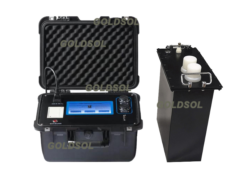
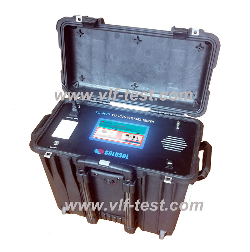
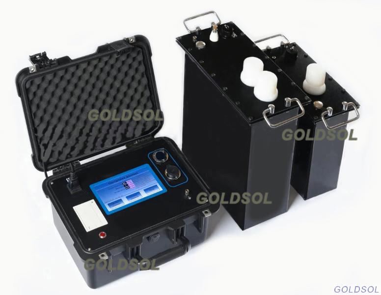
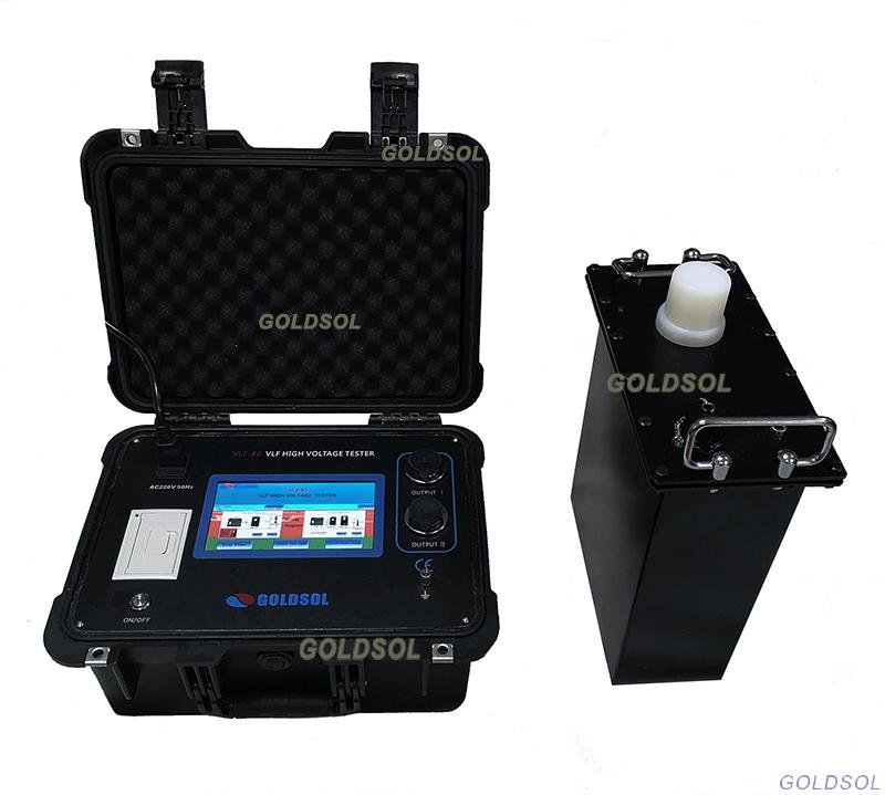
AC Testing of cables and electrical apparatus
is now easier than ever if using our VLF High Voltage Tester !
VLF testers are suitable for testing cables, transformers, switchgear,rotating machinery, and other electrical apparatus.
VLF Advantage:
Technical parameters
1.Power: 220V ± 10% AC, 50/60 Hz, single phase; or 110V ± 10% AC, 50/60 Hz, single phase.
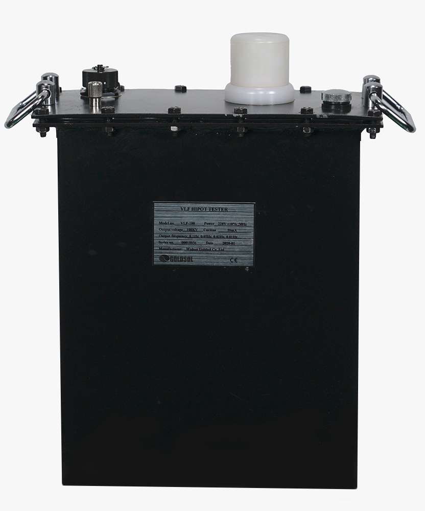
2. AC Output-Voltage (Peak):30KV, 40KV, 50KV, 60KV, 70KV, 80KV, 90KV, 100KV
3.Output frequency: 0.1Hz,0.05Hz,0.02Hz, 0.01 Hz (4 scales)
4. Stability of frequency: Fluctuation < 0.5%
5. Measurement accuracy: ±3%.
6. Positive and negative voltage peak error: ≤3%.
7. Voltage waveform distortion: ≤5%
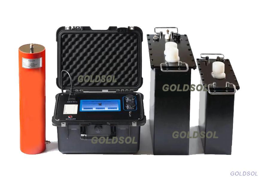
8. Construction: In two units: Control unit and Booster.
9. Ambient conditions of use: temperature Indoor and outdoor : -10ºC ~ + 50ºC.
10. Humidity:≤85%
|
Model no |
Output Voltage/ Current (Peak) |
Load Capacity |
Control Unit |
Booster |
Power |
||
|
Capacitance/ Freuency |
Net Dim. (cm) |
Net Wt (kg) |
Net Dim. (cm) |
Net Wt (kg) |
|||
|
VLF-30 |
30KV/20mA |
0.1 Hz, ≤1.0µF 0.05Hz, ≤2.0µF 0.02Hz, ≤5.0µF 0.01Hz, ≤10.0µF |
40×24×31 |
6 |
34×16×30 |
25 |
1000W |
|
VLF-40 |
40KV/20mA |
0.1 Hz, ≤1.0µF 0.05Hz, ≤2.0µF 0.02Hz, ≤5.0µF 0.01Hz, ≤10.0µF |
40×24×31 |
6 |
44×18×37 |
40 |
1200W |
|
VLF-50 |
50KV/30mA |
0.1 Hz, ≤1.0µF 0.05Hz, ≤2.0µF 0.02Hz, ≤5.0µF 0.01Hz, ≤10.0µF |
40×24×31 |
6 |
44×19×37
|
45 |
1500W |
|
VLF-60 |
60KV/59mA |
0.1 Hz, ≤0.5µF 0.05Hz, ≤1.0µF 0.02Hz, ≤2.5µF 0.01Hz, ≤5.0µF |
40×24×31 |
6 |
45×20×38
|
45 |
2000W |
|
VLF-70 |
70KV/59mA |
0.1 Hz, ≤0.5µF 0.05Hz, ≤1.0µF 0.02Hz, ≤2.5µF 0.01Hz, ≤5.0µF |
40×24×31 |
6 |
45×20×38 34×16×30 |
45+25 |
2500W |
|
VLF-80 |
80KV/59mA |
0.1 Hz, ≤0.5µF 0.05Hz, ≤1.0µF 0.02Hz, ≤2.5µF 0.01Hz, ≤5.0µF |
40×24×31 |
6 |
45×20×38 34×16×30 |
45+25 |
3000W |
|
VLF-90 |
90KV/59mA |
0.1 Hz, ≤0.5µF 0.05Hz, ≤1.0µF 0.02Hz, ≤2.5µF 0.01Hz, ≤5.0µF |
40×24×31 |
6 |
46×22×38 45×20×38 |
45+45 |
3500W |
|
VLF-100 |
100KV/59mA |
0.1 Hz, ≤0.5µF 0.05Hz, ≤1.0µF 0.02Hz, ≤2.5µF 0.01Hz, ≤5.0µF |
40×24×31 |
6 |
50×25×40 45×20×38 |
45+45 |
4000W |
Accessories

Contact: Mr.Luo
Phone: 86 13071289809
Tel: 86-27-82423362
Email: goldsol@foxmail.com
Add: No.128, Sanyang Road,Hankou Wuhan