Language:
 ∷
∷

∷
 ∷
∷
Home > Lightning Impulse Generator
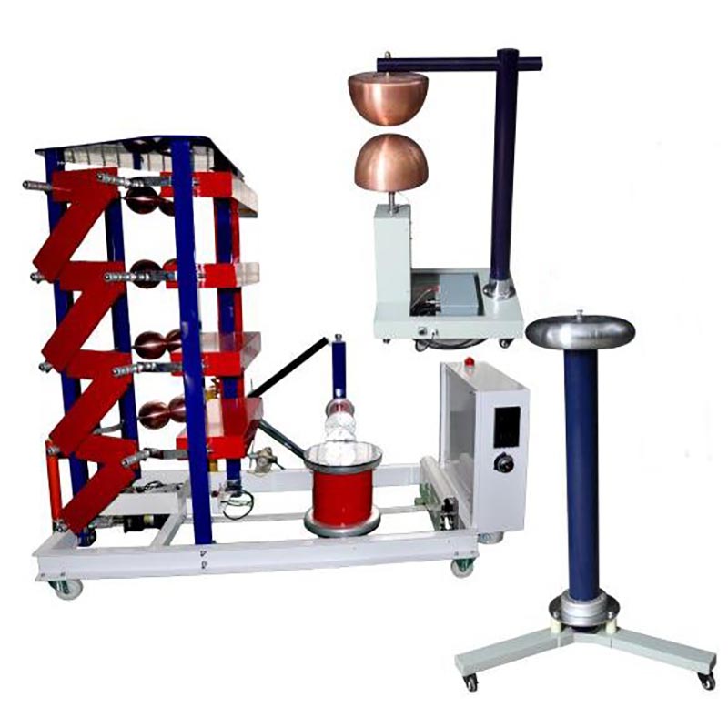
Application
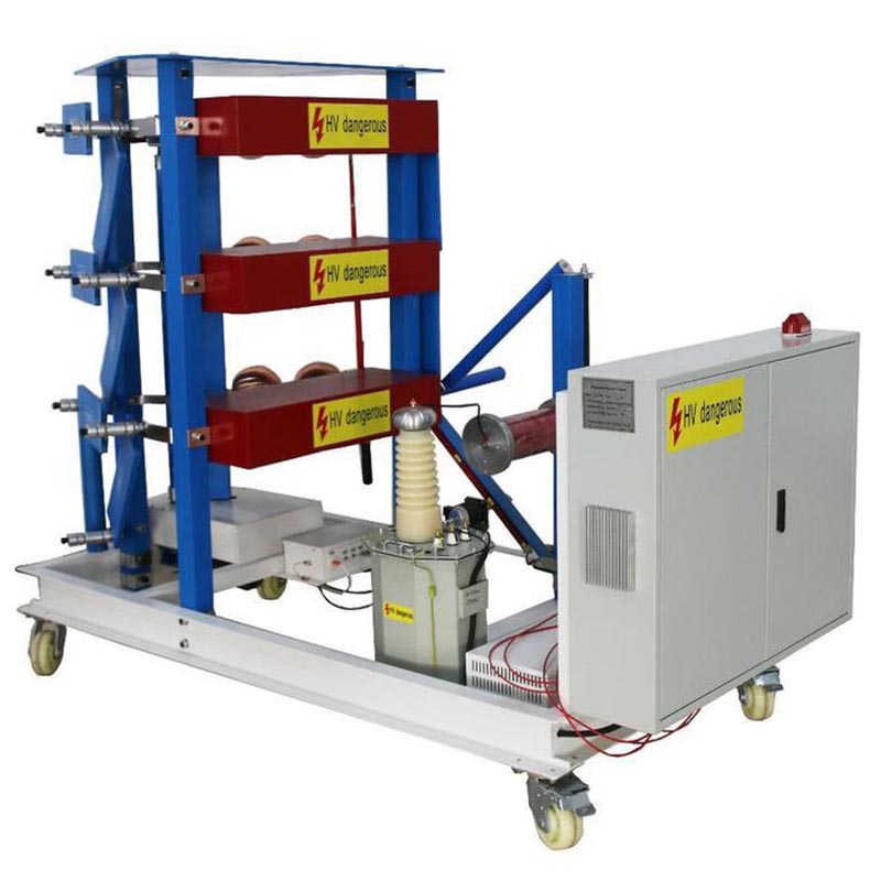
This lightning impulse voltage generator test system device is mainly suitable for testing Insulators,transformers, switches,Arresters and bushes with voltage levels ≤ 36kV for standard full lightning impulse voltage.
Woking condition:
1.Altitude≤2000m
2.Environment temperature: -15℃~50℃
3.Relative humidity≤90%
4.Installation place: indoor type, movable
5.Ground resistance<0.5Ω
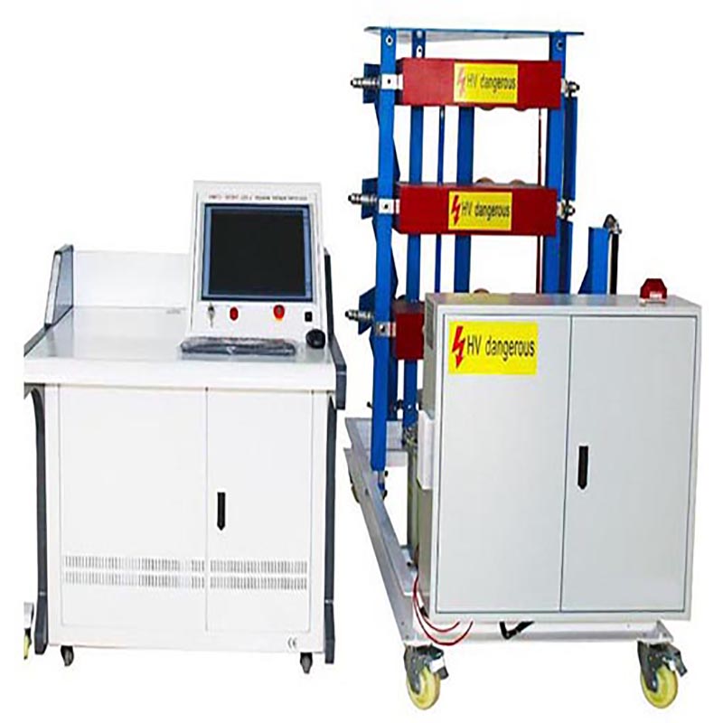
Test equipment included in the test system(Model: DWCJ-300KV/15KJ)
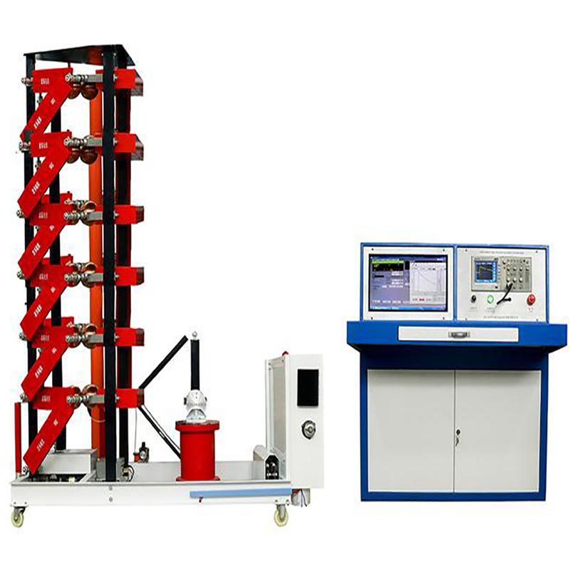
300KV/15KJ Full wave impulse device, 300kV Chopping device, 300KV Capacitive voltage divider, 100KV/50mA Rectifier Transformer, Measurement&control system(including Lighting impulse voltage Test Bench, TDS3012C Oscilloscope, IPM-24 Peak volmeter, 1 set Attenuator , printer, control&measurement software, etc.)
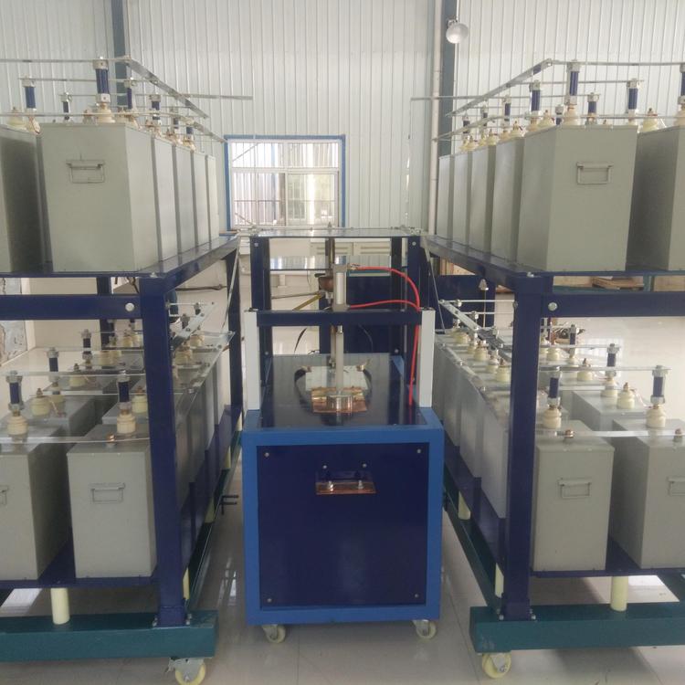
1. Impulse voltage generator (300kV/15kJ)
1)Main technical parameters
2)Nominal lightning impulse voltage: 300kV
3)Nominal capacity (energy): 15kJ
4)Number of stages/ Capacity per stage: 3 /5kJ
5)Rated capacitance: 1.0μF
6)Voltage per stage: ± 100kV
7)Output waveform:
- 1.2μs ±30% / 50μs±20% standard lightning impulse voltage full wave, efficiency ≥ 90%
- 250±20% / 2500±60%μs standard lightning impulse operating wave.
8)Min. output voltage≤10 %Un
9)Generator efficiency≥ 90%;
10)Triggering range: ≥ 20%
11)Working Duration:
Continuous operation >70%Un, charge&discharge every 90s
Continuous operation <70%Un, charge&discharge every 60s
Instability of output peak voltage≤1.0 %, the lowest output ≤10% of the nominal voltage of the device.
12)Malfunction rate while synchronous discharge<2 %
13)Ignition range: 10%~100%
14)Chopping device can produce cut-off lightning wave with a cut-off time of 2 ~ 6 μ s, and the dispersion of the cut-off wave is less than 100ns.
15)Base: 2.5m × 1.7m, caster moving.
16)Height: About 1.5m. Weight: about 650kg
2. Rectifier charging power supply
1)Model No.: LGR-100/50
12)Rated voltage: Un = 100kV DC (Positive or negative polarity)
13)Rated current: In = 50mA (Under rated voltage)
13)Voltage control: Controllable constant current charge, regulate range 0~100% Un
14)Polarity conversion: Auto convert path of high voltage silicon stack
15)Input voltage: 220V, single-phase
16)Frequency: 50/60Hz
17)Power supply capacity: 5kVA
18)power supply resistance: 3 pcs
3. Low damping capacitive voltage divider
1)Model: 300kV/300pF
2)Rated voltage: 300kV
3)Rated capacitance: 300pF
4)Stage of capacitor: 1 stage
5)Capacitance per stage: 300pF
6)Square wave response: Partial response time is less than 100ns, overshoot is less than 20%
7)Voltage division uncertainty: Less than 1%
4. Chopping device
1)Rated Voltage: 300kV
2)Sphere gap type: Ф300mm
3)Time delay mode: 2-6µs time delay adjustable circuit provide chopping trigger pulse.
4)Chopping wave dispersibility: Chopping wave time standard error is less than 0.1µs.
5)Sphere gap Qty: 2 pcs
6)Chooped wave resistance 1 pc
5. Controller (Signal analyze auto-testing system)
1)Waveform test: TDS3012C digital oscilloscope
Max. sample rate 1.0GS/s, 100MHz bandwidth, resolution 8bit
Record length 2.5K byte, 2 channels
2)Waveform analyzation:
Industrial control computer and LCD display
Impulse test software
Display and calculate impulse waveform parameters
Waveform comparison function
Waveform amplification, shrink and translation
Store and invoking of waveform
Auto-generated test report in picture format
6. Accessories
1)High performance 100 times specialized attenuator 2 pcs
2)Isolation filter shielding design
3)Wave head resistance 3 groups
4)Wave tail resistance 3 groups
7. Standard
IEC 60060-1
IEC 60076-3
IEC 62271-1
IEC 62271-200
Test transformer (JB / T9641-1999)
GB1094-2003 power transformer
GB / T509-1997 power transformer test guide
DL / T596 / 1996 code for preventive test of electric power equipment
GB311.1-1997 insulation coordination of high voltage transmission and transformation equipment
GB / T16927.1-1997 high voltage test technology general test requirements
GB / T16927.2-1997 high voltage test technology measurement system Digital recorder for high voltage impulse test
ZB F24 001-90 implementation rules for impulse voltage measurement
GB191 packaging and transportation marks
JB / T563 technical conditions for ordering coupling capacitors and capacitor voltage dividers
GB4208 enclosure protection level
GB813-89 oscilloscope and peak meter for impact test
GB7449-87 test guide for lightning impulse and operation impulse of power transformers and reactors
JB / T501 power transformer test guide
Transformer test technology (JB / t501-1991)
IEC60-1 and IEC60-2 high voltage test technology
GB50150-91 standard for hand over test of electrical equipment in electrical equipment installation engineering
DL / T557-94 high voltage line insulator steep wave impact test, definition, test method and criteria
DL / T 848.5-2004 general specification for high voltage test equipment Part 5: impulse voltage generator
DL / T 846.1-2003 general specification for high voltage test equipment Part 1: high voltage divider measurement system
DL / T 846.2-2004 general specification for high voltage testing equipment Part 2: impulse voltage measuring system
Contact: Mr.Luo
Phone: 86 13071289809
Tel: 86-27-82423362
Email: goldsol@foxmail.com
Add: No.128, Sanyang Road,Hankou Wuhan